Darpa Challenge: Drones that can carry 4x their weight.
To redesign a DJI-class drone to lift 400% of its own weight (a 4:1 payload-to-weight ratio), we must move beyond incremental improvements and into the realm of aggressive mass reduction and high-energy density propulsion. Here are ideas to achieve that.
As an engineer, I would implement the following 30-point redesign protocol, focusing on the "structural carbon fiber wrapped titanium core" and "detail reduction" strategies you requested.
Structural & Material Redesign
Topology Optimization (Generative Design): Use "Structural Detail Reduction" software (like Altair Inspire or Ansys Discovery) to remove every milligram of non-load-bearing material, resulting in a "skeletal" organic frame.
Titanium-Carbon Composite Backbone: A Grade 5 Titanium (Ti-6Al-4V) hollow rod serves as the central "spine," providing immense shear strength.
Filament-Wound Carbon Fiber Sleeving: The titanium core is overwrapped with high-modulus (M46J) carbon fiber to provide superior rigidity and prevent buckling.
Lattice Infill 3D Printing: Use Scalmalloy (aluminum-scandium) for the motor mounts, printed with a gyroid lattice infill to maximize the strength-to-weight ratio.
Deleted Enclosures: Remove all aesthetic plastic shells. The "skin" is replaced by a tensioned, ultra-thin Vectran fabric or a 5-micron Mylar wrap for aerodynamics.
Load-Bearing Battery Casing: The battery is no longer a "passenger"; its carbon-fiber casing acts as a structural member of the airframe. (Or a Snap on modular battery compartments might make replacing damaged parts easier? Or swapping charged for non charged batteries)
Solderless Integrated PCB: The flight controller and ESCs (Electronic Speed Controllers) are integrated into a single high-density board that serves as a structural plate.
Titanium Fasteners: Replace every steel screw with hollowed-out titanium or 7075 aluminum bolts. Or Use Superglue with a substrate of titanium powder.
Propulsion & Aerodynamics
Axial Flux Motors: Shift from traditional radial motors to Axial Flux motors, which offer higher torque density and a thinner profile for the same weight.
Cryogenic Motor Cooling: Use a small phase-change cooling loop to allow motors to run at 200% of their rated current without melting the windings.
Super-Shrouded Propellers (Ducting): Use ultra-light carbon ducts to create "static thrust" augmentation, effectively increasing lift by 15-20% through the Coanda Effect.
Toroidal Propeller Geometry: Replace standard blades with loop-shaped toroidal propellers to eliminate tip vortices and recapture wasted energy as lift.
Variable Pitch Hubs: Implement a lightweight collective pitch mechanism (like a helicopter) so motors can stay at their peak RPM/Efficiency band regardless of load.
Plasma Actuators: Use Dielectric Barrier Discharge (DBD) plasma actuators on the leading edges of the arms to "re-attach" airflow and reduce drag/turbulence.
Boundary Layer Ingestion: Shape the frame so the propellers pull air directly over the electronics, cooling them while smoothing out the intake flow.
High-KV Low-Voltage Overdrive: Utilize high-KV motors with a 12S or 15S battery system for extreme RPM bursts during the lift phase.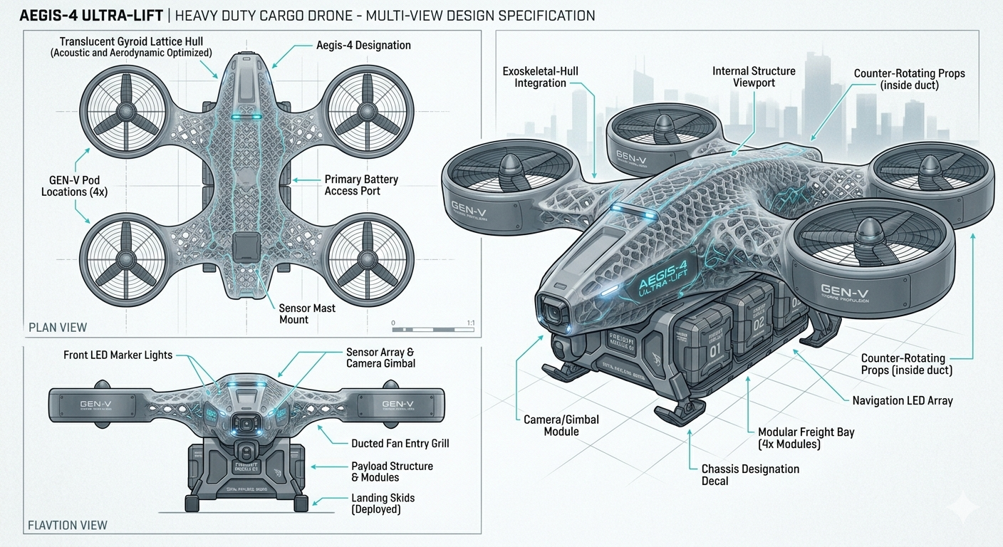
Energy & Electronics
Solid-State Batteries: Replace LiPo with Solid-State Lithium-Metal cells, which can offer energy densities near 500 Wh/kg (vs. the current ~250 Wh/kg).
Gallium Nitride (GaN) ESCs: Use GaN transistors in the speed controllers to reduce heat sink size by 60% due to higher switching efficiency.
Laser Power Beaming (Unconventional): For static lifting, use a ground-based laser to beam power to a photovoltaic receiver on the drone's belly, removing battery weight entirely.
Hydrogen Fuel Cell Hybrid: Use a micro-hydrogen fuel cell for base hover power, with a small "supercapacitor" buffer for high-thrust maneuvers.
Optical Fiber Wiring: Replace heavy copper signal wires with plastic optical fiber to reduce EMI and weight.
Structural Capacitors: The frame itself is layered to act as a capacitor, storing "burst" energy for emergency lift.
Cutting-Edge Engineering Tricks
Distributed Electric Propulsion (DEP): Instead of 4 large motors, use 8 smaller, high-speed units. Small propellers have lower rotational inertia and higher disc loading efficiency.
Active Flow Control (Pulsed Jets): Tiny air nozzles on the propeller blades pulse to prevent stall at high angles of attack during heavy lifting.
Ground Effect Skirts: For the initial lift-off, use retractable thin-film skirts to trap a high-pressure bubble under the drone.
Ionic Wind Augmentation: Use high-voltage grids to ionize air and accelerate it downward, providing a "silent" supplementary lift force.
Counter-Rotating Coaxial Arrays: Stack two propellers per arm to double the thrust area without increasing the drone’s footprint.
Tensile Stay-Wires: Use Kevlar or Dyneema "rigging" (like a suspension bridge) to allow the arms to be much thinner while resisting the upward bending force of 4x weight.
Bio-mimetic "Owl" Serrations: Add serrated edges to propellers to reduce noise and allow for higher RPM operation in noise-sensitive environments.
Dynamic Center of Gravity (CoG) Shifting: Use a motorized rail for the battery so the drone can "lean" into the lift, optimizing the thrust vector of each motor.
Engineering Note: To achieve a 4:1 lift-to-weight ratio, the "Dry Weight" of the drone must be minimized to the point where it feels fragile to the touch. The Titanium-Carbon skeletal frame is the only way to ensure it doesn't snap under the massive G-forces generated by the high-RPM motors required for such a feat.
Ideas:
For a drone frame that needs to be lightweight yet capable of carrying a 4:1 payload-to-weight ratio, you aren't just looking for "porosity"—you are looking for high specific stiffness.
1. Comparing the Structures
Choosing the right geometry is a trade-off between predictable physics and natural efficiency.
| Structure Type | Strength-to-Weight | Impact Resistance | Printability |
|---|---|---|---|
| Hexagonal (Honeycomb) | Excellent (Uniaxial) | Moderate | Easy |
| Organic (Gyroid/TPMS) | Superior (Isotropic) | High | Excellent (Self-supporting) |
| Atomic Mimicry | Variable | Low (Brittle) | Difficult |
The Hexagonal Approach
Hexagons are "stretch-dominated" structures. They are incredibly stiff if the force is coming from a specific direction (like the vertical lift of a motor). However, they are "anisotropic," meaning if the drone crashes or takes a side-impact, the structure can buckle easily.
The Organic / Fibrous Approach (TPMS)
The current gold standard for high-end aerospace parts is the Gyroid or Schwarz P surface. These are "Triply Periodic Minimal Surfaces" (TPMS).
Why they win: They are mathematically optimized to have zero mean curvature at every point. This eliminates "stress concentrators" (sharp corners) where cracks usually start.
The Drone Advantage: Because they are "curvy," they distribute the weight of the 4x payload evenly throughout the entire frame rather than just along specific struts.
Atomic Mimicry (Lattice)
Mimicking the crystalline structure of elements (like the Diamond lattice) is common in medical implants. While very strong, these structures can be "bending-dominated," meaning the thin struts might flex under a heavy payload before the metal actually fails.
2. The Best Choice: The Gyroid Lattice
For your specific drone use case, a graded Gyroid structure is likely the best option.
Isotropic Strength: It handles forces from the motors, the payload, and potential crashes equally well.
Internal Routing: Because it is porous and interconnected, you can run wiring through the "pores" of the metal frame itself.
Heat Dissipation: Metal lattices act as massive heat sinks. You could technically use the frame to cool your ESCs (Electronic Speed Controllers).
3. How to Manufacture It
You mentioned "metal filament." It is important to distinguish between two methods:
Metal FDM (Filament): You print using a filament that is ~80% metal powder and ~20% plastic binder (like BASF Forward AM). You then have to "debind" and "sinter" it in a furnace. Warning: During sintering, the part shrinks by about 20%, which can warp complex lattices.
DMLS/SLM (Laser Powder Bed): This is the professional route. A laser melts pure metal powder (Titanium or Aluminum). This is the most reliable way to ensure the "porosity" doesn't result in hidden brittle spots.
To achieve the absolute minimum material usage (the "theoretical limit" of lightweighting), you are moving into the realm of Hybrid Composite-Lattice Engineering.
By combining high-stiffness longitudinal members (the rods) with a topological lattice (the 3D printed core), you create a structure that mimics the geometry of a bird’s bone: a hard, dense outer cortex with a marrow-like "trabecular" interior.
1. The "Exoskeletal" Strategy
To carry 4x the drone's weight with the least material, you should not put the rods in the center. Instead, you should place them at the periphery of your structural members.
In engineering, this is known as maximizing the Moment of Inertia. Material placed far away from the "neutral axis" (the center) does much more work to prevent bending than material in the middle.
The Ideal Configuration:
The Spine (Rods): Use the titanium/carbon fiber rods as the "outer rails" of your drone arms. Carbon fiber is world-class in tension (pulling), while titanium handles compression (crushing) without shattering.
The Webbing (Lattice): Use 3D printed metal to create a "shear web" between the rods. Instead of a solid block, print a Gyroid or Isotruss lattice that connects the rods. This prevents the rods from buckling or twisting.
2. Calculating the "Least Material"
To minimize mass, you want to eliminate Redundant Load Paths. In a standard drone frame, much of the material is "dead weight" because it isn't directly resisting the motor's torque or the battery's gravity.
The Minimum Material Hierarchy:
Primary Load Path (Rods): Should constitute ~60% of the total mass. These carry the primary bending moments from the motors.
Secondary Support (Lattice): Should be ~30% of the mass. This should be a "graded" lattice—dense near the motor mounts and thinning out (becoming more porous) as it moves toward the center of the arm.
Tertiary Skin (Optional): ~10% of the mass. A micro-thin aerodynamic skin.
3. Structural Comparison: Wrapped vs. Spaced
| Configuration | Material Efficiency | Reason |
|---|---|---|
| Wrapped Together | Low | Bundled rods behave like one thick rod. They are heavy and prone to bending as a single unit. |
| Strategically Spaced | High | Spacing rods apart (e.g., in a triangular or square truss) creates a "Virtual Beam." This allows you to achieve massive stiffness with almost zero weight in the center. |
4. The "Atomic Mimicry" Refinement
If you want to mimic an atomic structure for the "webbing" between your rods, the Lonsdaleite (Hexagonal Diamond) lattice is the most efficient. It uses 58% less material than a solid block to achieve the same compression resistance.
Summary of the "Ultralight" Build:
Chassis Shape: A "Tapered Box Truss."
Materials: 4x Titanium-sleeved Carbon Fiber rods at the corners.
Internal Matrix: A 3D printed Titanium Gyroid lattice with a volume fraction of only 5-10% (meaning 90-95% of the "solid" parts are actually air).
By using a graded lattice (where the "pores" get larger in areas of low stress), you can reduce the chassis weight by an additional 20-30% compared to a uniform porous structure.
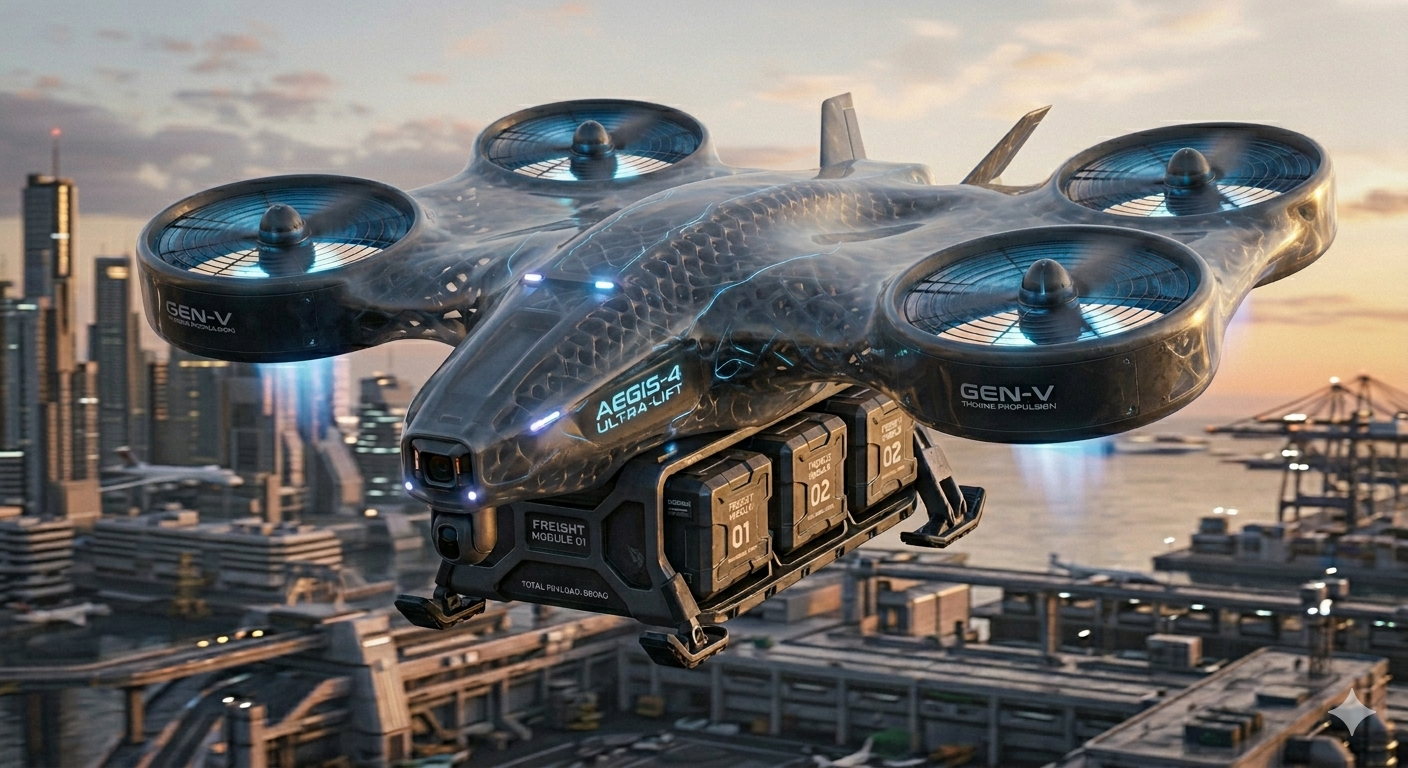
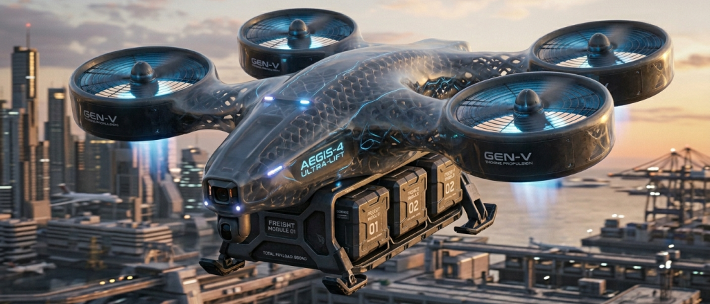
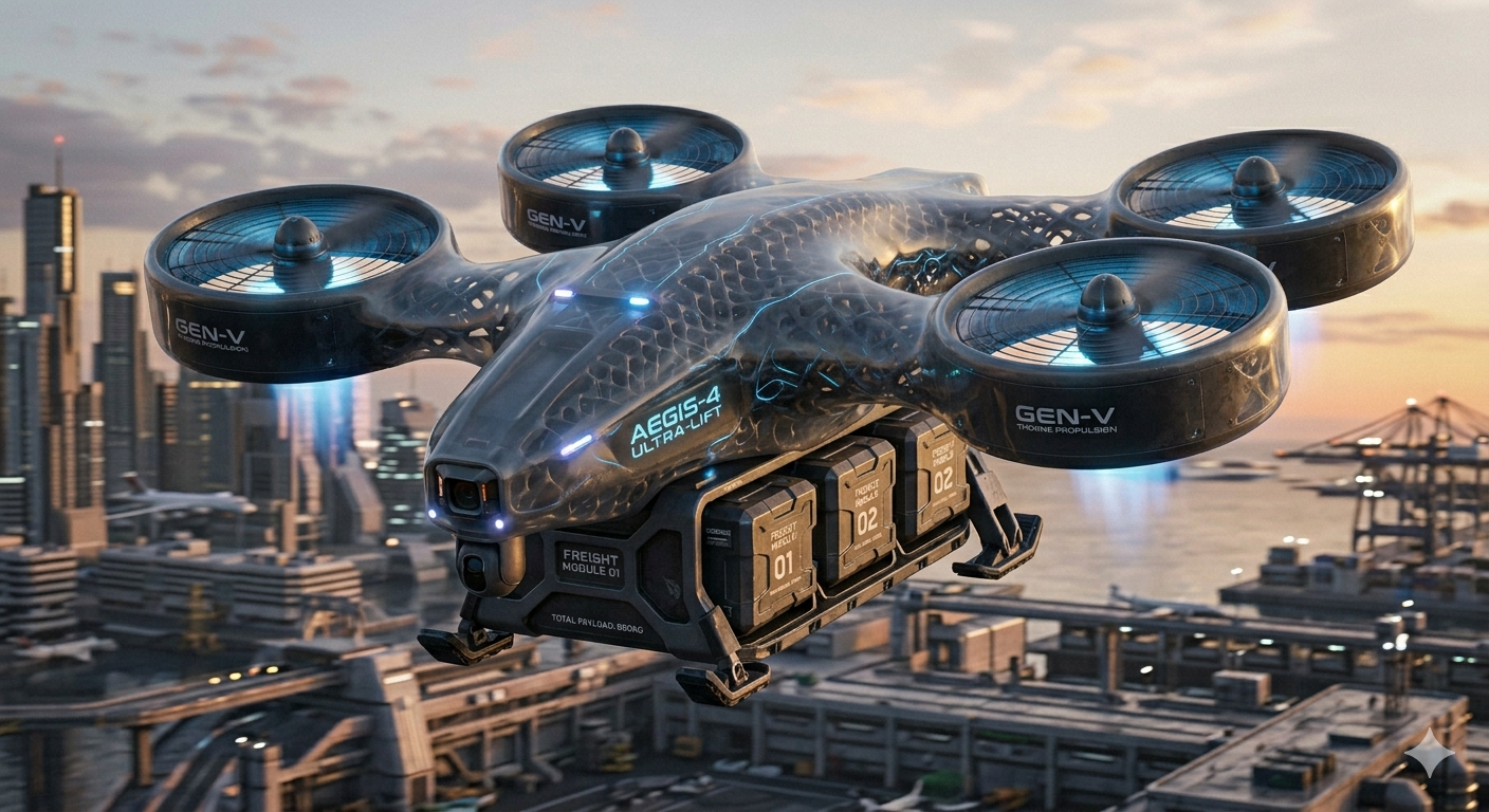
Here is a lifting body design: